RILYBOT 2
In August 1999 I experimented with robot designs that move on three wheels arranged in an equilateral triangle, and with complete rotational symmetry (i.e., the whole robot looks the same if rotated 120 degrees).
Here is my first successful construction based on that idea:
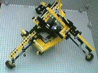
A general view (tilted so it would fit better in the viewframe)
Click here for building instructions
There are three "legs", each with a backbone consisting of two yellow 1x16 beams. Each leg is connected to the other two via cross-braces, which are black 1x12 beams. Each leg also supports a motor which directly (no gears) drives a wheel located at the bottom of the leg. Except for the RCX, the minifig "driver" and other decorations, the model is completely symmetrical.
This picture shows how I connected the beams at the top:
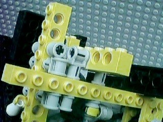
Three beams at mutually orthogonal angles
This picture shows two of the three main legs: they are the diagonal yellow beams. There is a lot of other stuff in the picture, but you should not in particular that there is a horizontal 1x12 black beam that is being used to connect the two legs together. There are a total of three of these beams, each connected exactly the same way:
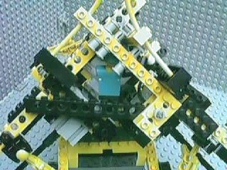
Notice the horizontal 1x12 black beam that connects two legs
Here is a better look at one end of a cross-brace:
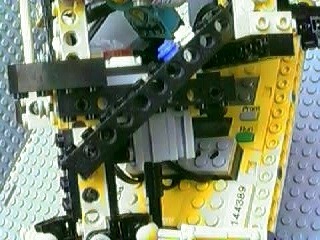
Cross-brace
The cross-brace is the black beam that runs diagonally in this picture. Behind it is a shorter black beam ("horizontal" in this picture) that is helping hold one of the motors. You can also see the motor's axle. Behind all that you can see two gray 1x10 plates and the ends of two yellow 1x16 beams; these are holding the RCX.
The other end of each 1x12 brace is held between two yellow 2x4 technic plates, which also form the top part of the support for a motor:
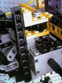
Other end of a brace, and motor support
The bottom end of each axle is connected like this:
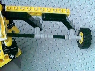
Bottom end of axle
There are two angle beams connected to the 1x16 yellow beam with friction connector pegs (the black connector pegs) and the other end of each angle beam has connectors to support the axle while allowing it to turn freely.
The RCX hangs underneath the three motors and is attached with four struts using this design:
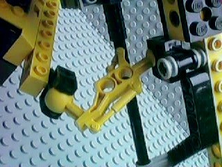
An RCX support strut
Each of the four struts is positioned slightly differently because the angles are different, but all four struts use the same parts (a Throwbot ankle socket at each end connected by a Throwbot leg). Because there are four struts and only three main legs to connect to, two of the struts share one of the main legs.
Just For Fun
Here is the robot's driver:
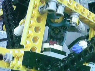
Minidave at the controls
He has his left hand on the yaw control, which makes the robot turn around its axis. His right hand is on the surge-sway control, a joystick that moves the robot forwards/back and side-to-side. He has complete control of all three degrees of freedom. In front of Minidave is his infrared monitor, which displays messages I send with the IR remote and received via this (completely decorative) antenna:
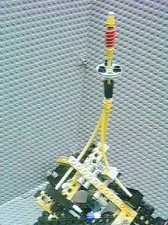
The antenna
Usually Minidave does what I tell him to, but not always. The big blue and white buttons perform emergency shutdown and eject, respectively.
How the Movement Works
This robot moves by turning two or more wheels at once. Call the legs A B and C (doesn't really matter which is which). If you run all three in the same direction, the robot will turn.
If you run A and B clockwise, the robot will sort of "pivot" around the point where wheel C touches the ground. (C can't move because the motor is in "braked stop" mode, resisting movement.) If you then stop A and B, and run B and C counter-clockwise, it will pivot around A in the opposite direction. If you repeat this over and over again, the robot will "wiggle" and gradually move forwards in the process.
I also discovered that on certain smooth surfaces you can make it move forwards simply by running two motors in opposite directions and leaving the third motor stopped. There were also a bunch of compound movements (like turning and moving laterally at the same time) and some movements (like running just one motor) that didn't do much of anything.
RILYBOT 2 building instructions
LEGO® creations index
The graph paper in my newer photos is ruled at a specing of 1 LSS, which is about 7.99 mm.
This site is not affiliated with the LEGO® group of companies.
LEGO®, Duplo®, QUATRO®, DACTA®, MINDSTORMS®, Constructopedia®, Robotics Invention System® and Lego Technic®, etc. are trademarks or registered trademarks of LEGO Group. LEGO Group does not sponsor, authorize or endorse this site.
All other trademarks, service marks, and copyrights are property of their respective owners.
If you want to visit the official LEGO® site, click here
Parts images are from LUGNET. On this page they explicitly give permission to link to the images:
Note: you may link (as in, Yes, it's OK) directly to these parts
images from an off-site web page.
This page was written in the "embarrassingly readable" markup language RHTF, and was last updated on 2012 Dec 30.
 s.27
s.27